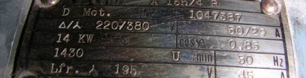
- Power at 400 V a.c.: 16,000 W
- Min. wind speed: 0.3m/s
- Max wind speed: 16.0 m/s (small cross-section)
- Max wind speed: 12.0 m/s (large cross-section)
- The wind speed control is infinitely variable.
- Height above floor level 0.9m
- Large cross-section (BxH) 2.00x1.00 m
- Small cross-section (BxH) 1.20x1.00 m
- Length 2.00m
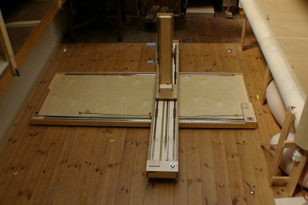
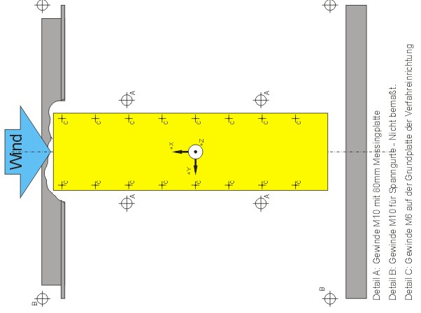
The positioning jig has a base plate with a grid array (500 x 250 mm) of M6 thread
attachment points, suitable for any type of experiment.
When operated in the small cross-sectional mode in the speed range 4 to 16 m/s, the airflow quality is always better than
(Geschwindigkeitprofil = Speed Profile):
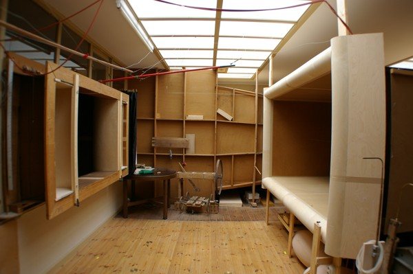
Samples brought for testing in the Focke Wind Tunnel must be introduced through a narrow passage with corners and a door 90 cm wide. Prior to assembly, individual components should not be larger than 1200 x 800 (as seen in plan view) and not more than 1600 mm high. A trolley capable of carrying up to 400 kg is available for use in the wind tunnel hall.